Preface
The purpose of level calibration is to align the levels in the digital domain with the actual levels cut onto the disk. After a successful calibration, the playback level on disk should match the disk level predicted by the software.
Prerequisites
Before starting the level calibration process, ensure the following:
- Complete Pitch Calibration and Width Calibration before starting the level calibration procedure.
- Obtain the
.headcalibration file specific to your cutter head. - Verify your playback path accuracy by playing a test record with a NAB reference tone (5 cm/s stereo @ 1 kHz) and checking the hardware LEVEL meters E to show 0 dB peak level in both channels.
- Prepare a lacquer for a test cut; the position of the cut on the disk is not critical.
Abbreviations
- SDMS
- Sillitoe Disk Mastering System hardware
- STC
- Space / Time Control software
References
Calibration Procedure
Source Gain Adjustment
The first step of the calibration is to find a suitable DAC gain setting for the cutterhead.
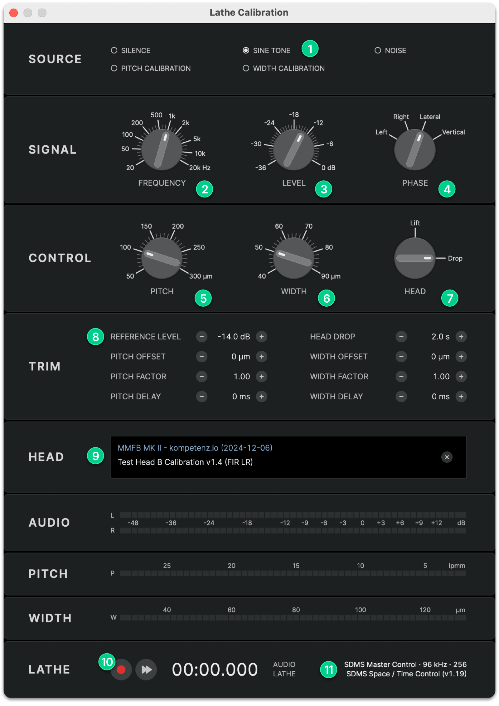
- Launch STC and open the Lathe Calibration dialog
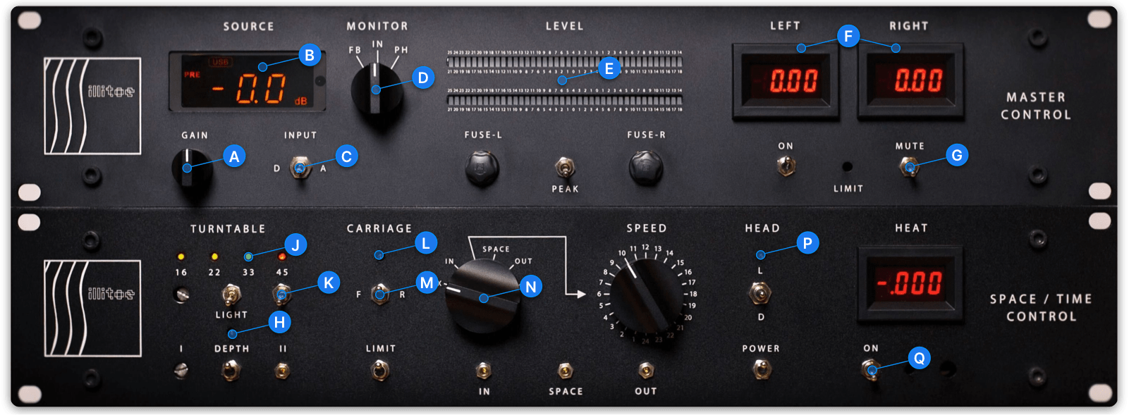
- Confirm your SDMS Master Control and Space / Time Control hardware modules are connected 11
- Select SINE TONE 1 as the source and set the following SIGNAL parameters:
- FREQUENCY 2 1 kHz
- LEVEL 3 −14 dB
- PHASE 4 Lateral
- Set the REFERENCE LEVEL 8 to its default value of −14.0 dB
- Load your
.headcalibration file and verify it is displayed correctly in the HEAD 9 section - Disable automation for DEPTH H, CARRIAGE L and HEAD P (LED buttons OFF)
- Set the INPUT C selector to (D)igital
- Use the GAIN A knob to adjust the SOURCE LEVEL B to −30 dB
When ready:
- Unmute the cutter head G
- Press the REC 10 button to start the test tone playback
- Slowly increase GAIN A and monitor the LEFT and RIGHT F current meters
- Ideally, you should reach a SOURCE LEVEL B of −10 dB without exceeding 250 mA on the LEFT and RIGHT F current meters. If 250 mA is reached at a lower SOURCE LEVEL , keep the GAIN A at that level
- Stop the playback by pressing STOP 10 and mute the cutter head G
- Note the current SOURCE LEVEL B as your base source level value
Sine Tone Calibration
Next, cut a reference sine tone with that GAIN setting and play it back to determine the REFERENCE LEVEL in STC :
- Set the following parameters in the CONTROL section:
- PITCH 5 100 µm
- WIDTH 6 50 µm
- HEAD 7 Drop
- Enable automation for DEPTH H, CARRIAGE L and HEAD P (LED buttons ON)
- Ensure the carriage direction M is set to F(orward)
- Set the TURNTABLE SPEED J to 33
- Switch on TURNTABLE K and VACUUM & STYLUS HEAT Q
- Unmute the cutter head G
- Press REC 10 and cut the test tone for 10…30 seconds
- Press STOP 10 to end the cut and mute the cutter head G
When finished:
- Switch the MONITOR D path to PH(ONO)
- Play the test tone back on the SDMS and note the values on the SDMS Master Control hardware LEVEL E meter.
- Adjust the REFERENCE LEVEL 8 based on the playback meter value relative to 0 dB:
- If playback level > 0 dB, lower the reference level by the offset
- If playback level < 0 dB, raise the reference level by the offset
Observed Playback Level = +3 dB
REFERENCE LEVEL = −14.0 dB − 3 dB = −17.0 dB
Level Calibration Project
To refine your calibration, use the Level Calibration Project, a short test groove with two special sine sweep signals ranging from 100 Hz to 1 kHz.
You can download the Level Calibration groove file here (2.5 MB).
Cutting The Project
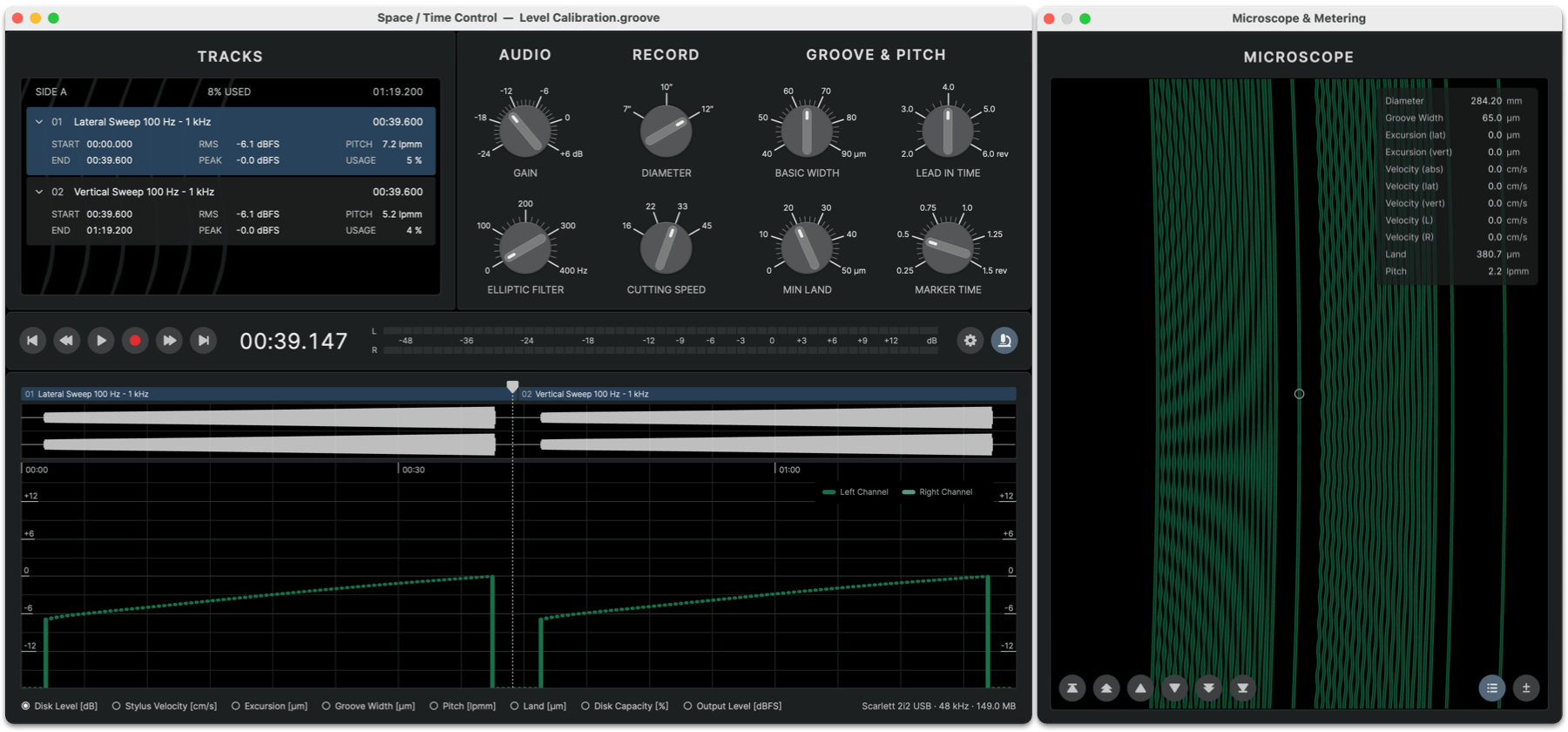
- Launch STC and open the project
Level Calibration.groove - Adjust the AUDIO GAIN control in STC until the Disk Level graph shows a maximum of 0 dB ; leave all other settings at their defaults.
- Enable automation for DEPTH H, CARRIAGE L and HEAD P (LED buttons ON)
- Ensure the carriage direction M is set to F(orward)
- Unmute the cutter head G
- Move the playhead in STC to 00:00.000
- Select File > Record Project to open the Cut Project dialog
- Hold down the SHIFT key and click REC to start the cut. (Holding the SHIFT key will skip the lead-in and cut only the program, thus saving lacquer space.)
Evaluation
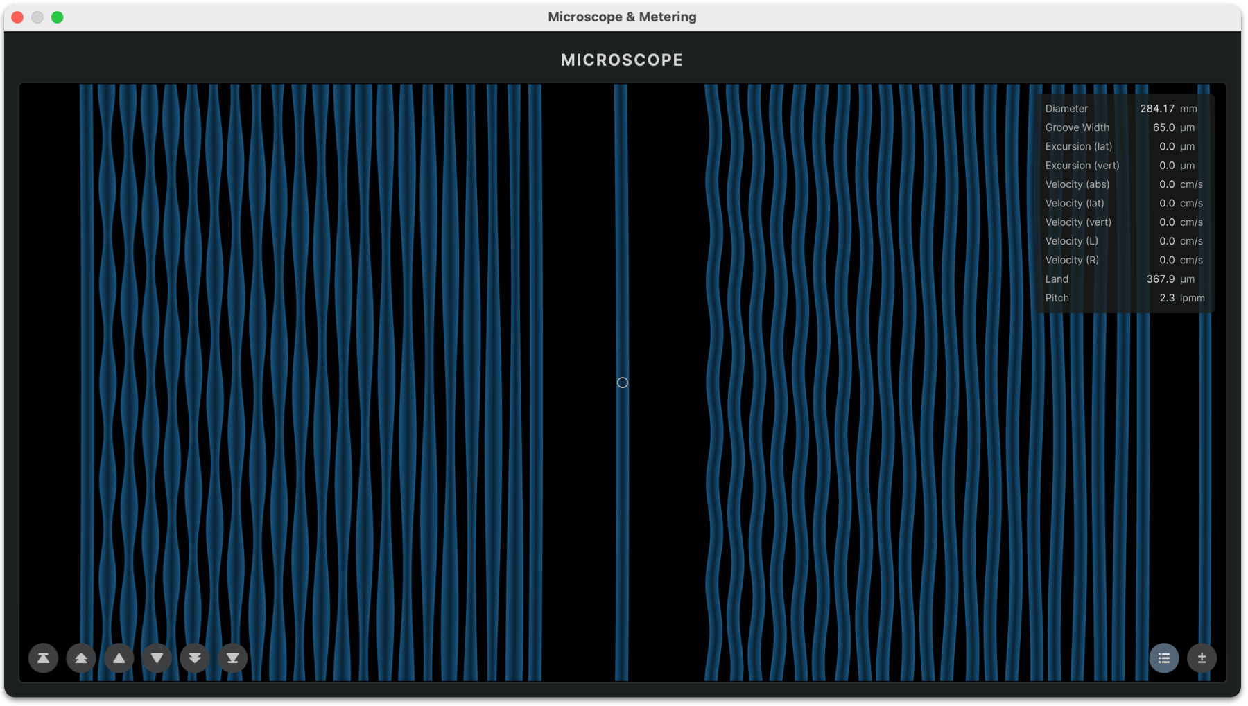
Inspect the groove under the groove inspection microscope and check the following items:
- Neighboring grooves should always have minimal land of 5…10 µm; there should be no kissing grooves or overcuts
- In the second track with vertical stylus movement, the groove should always alternate between approximately the same minimum and maximum groove width. Check the Groove Width analysis graph or MICROSCOPE view in STC to see what width values to expect in the cut
- If the variation in width of the vertical groove is greater than predicted or you see kissing grooves, lower the REFERENCE LEVEL 8 in the Calibration Dialog until the Groove Width analysis graph matches your measurement
- If the variation in width of the vertical groove is less than predicted and the minimum land between grooves is wider than the MIN LAND setting, raise the REFERENCE LEVEL 8 in the Calibration Dialog until the Groove Width analysis graph values match the measurement
Troubleshooting
- Once calibrated, always keep the SOURCE LEVEL B of the SDMS Master Control at the level determined during calibration. Adjusting the hardware GAIN A after calibration will cause a mismatch between predicted disk level and actual disk level, potentially leading to overcuts due to miscalculated pitch signals
- If you need to adjust the SOURCE LEVEL B after calibration, you must also adjust the REFERENCE LEVEL 8 in STC by the inverse offset
Calibrated Source Level = −15 dB
Calibrated Reference Level = −14 dB
Added Gain = + 6 dB
=> New Source Level = −15 + 6 = −9 dB
=> New Reference Level = −14 − 6 = −20 dB
