Preface
The goal of groove width calibration is to align the depth signal sent by the software with the actual movement of the dynamic depth adjustment mechanism.
The SDMS head suspension box enables both mechanical and electrical adjustments for groove depth. The mechanical adjustment sets a base groove depth, while the electromagnetic system allows for dynamic and fine-grained depth control, which can be automated by the software.
Prerequisites
- Complete the Pitch Calibration procedure before starting width calibration
- Complete the SDMS "Silent Groove Instructions" to establish a manual w calibration for a baseline groove width of approximately 50 µm
- Setup you system for lacquer cutting; plastic blanks are not suited well for width calibration.
- Ideally, cut the calibration signals at a diameter Ø < 260 mm.
Abbreviations - SDMS
- Sillitoe Disk Mastering System hardware
- STC
- Space / Time Control software
References
Calibration Procedure
Manual Baseline Cut
- Disable CARRIAGE L and HEAD P automation (LED buttons OFF)
- Enable DEPTH H automation (LED button ON)
- Perform a manual test cut of a silent groove for 3…5 revolutions
- Measure the average groove width using the groove inspection scope and record it as your GROOVE WIDTH BASELINE
Groove Width Calibration
Prepare STC and SDMS for the calibration cut:
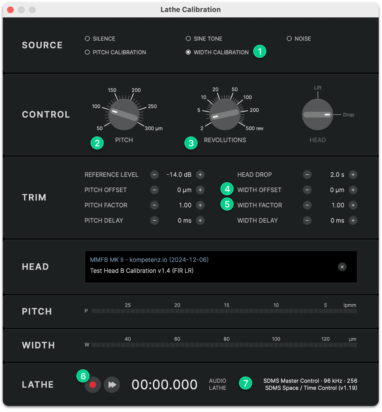
- Launch STC and open the Lathe Calibration dialog
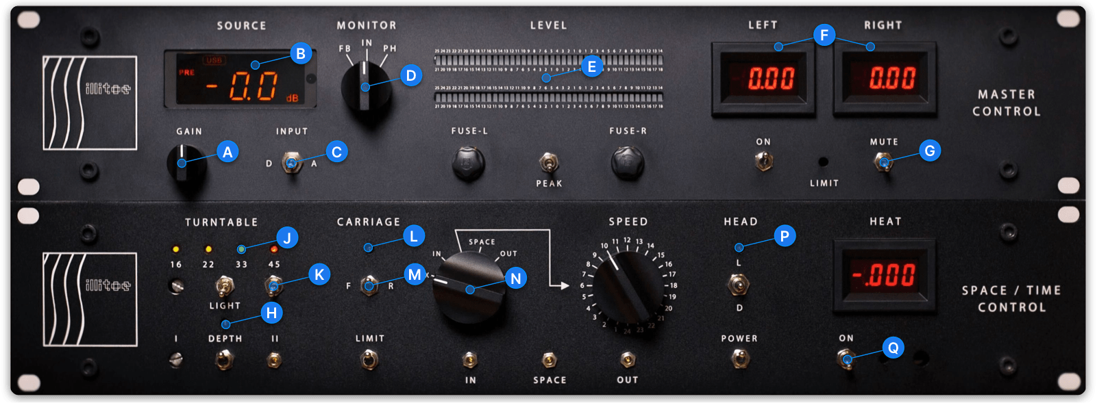
- Confirm your SDMS Master Control and Space / Time Control hardware modules are connected 7
- Enter your GROOVE WIDTH BASELINE value as a negative WIDTH OFFSET 4
(Example: If you manually cut a 50 µm wide groove, enter −50 µm as WIDTH OFFSET 4) - Set the WIDTH FACTOR 5 to 2.00
- Select WIDTH CALIBRATION 1 as the source and set:
- PITCH 2 to 100 µm
- REVOLUTIONS 3 to 3 rev
- Enable automation for DEPTH H, CARRIAGE L and HEAD P (LED buttons ON)
- Ensure the carriage direction M is set to F(orward)
- Set the TURNTABLE SPEED to 33 J
- Switch on the TURNTABLE K and VACUUM & STYLUS HEAT Q
When ready to cut:
- Press REC 6 to start the calibration cut
- The software will cut a groove with increasing width from 50 µm to 90 µm Each width will be held constant for the number of revolutions you set above (default: 3 rev)
- The test will stop automatically when complete
Evaluation of the results
- Inspect the groove using the groove inspection scope
- Measure the average width of each groove section and note the values in the table below
| EXPECTED WIDTH | MEASURED WIDTH |
|---|---|
| 50 µm | |
| 60 µm | |
| 70 µm | |
| 80 µm | |
| 90 µm |
Send your measured results to calibration@spacetimecontrol.com for review and evaluation of your WIDTH FACTOR and WIDTH OFFSET parameters.
Troubleshooting
Slight variations in lacquer thickness will create slightly wider or narrower grooves. The same is true after switching to a new stylus.
If you see a width offset in a test groove with a fresh lacquer or new stylus, you can correct the WIDTH OFFSET to recalibrate the system using the following formula:
Expected Groove Width = 50 µm
Measured Groove Width = 55 µm
Width Offset Delta = 50 µm − 55 µm = −5 µm
