- Introduction
- Track List
- Transport and Metering
- Layout Parameters
- Groove Processing
- Groove Analysis
- Application Settings Dialog
- Lathe Calibration Dialog
- Cutting Dialog
- Miscellaneous
Introduction
Space / Time Control (STC) is the analysis and control software for the Sillitoe Disk Mastering System (SDMS).
It enables precise and efficient cutting by supporting the cutting engineer through the following key steps:
- Defining the audio program for a side of the record
- Finding the optimal groove layout and cutting parameters
- Analyzing groove geometry and playback dynamics
- Automating the SDMS cutting process
This manual provides a reference for all software elements and settings.
For a step-by-step workflow guide, please refer to our tutorial videos at spacetimecontrol.com
Track List
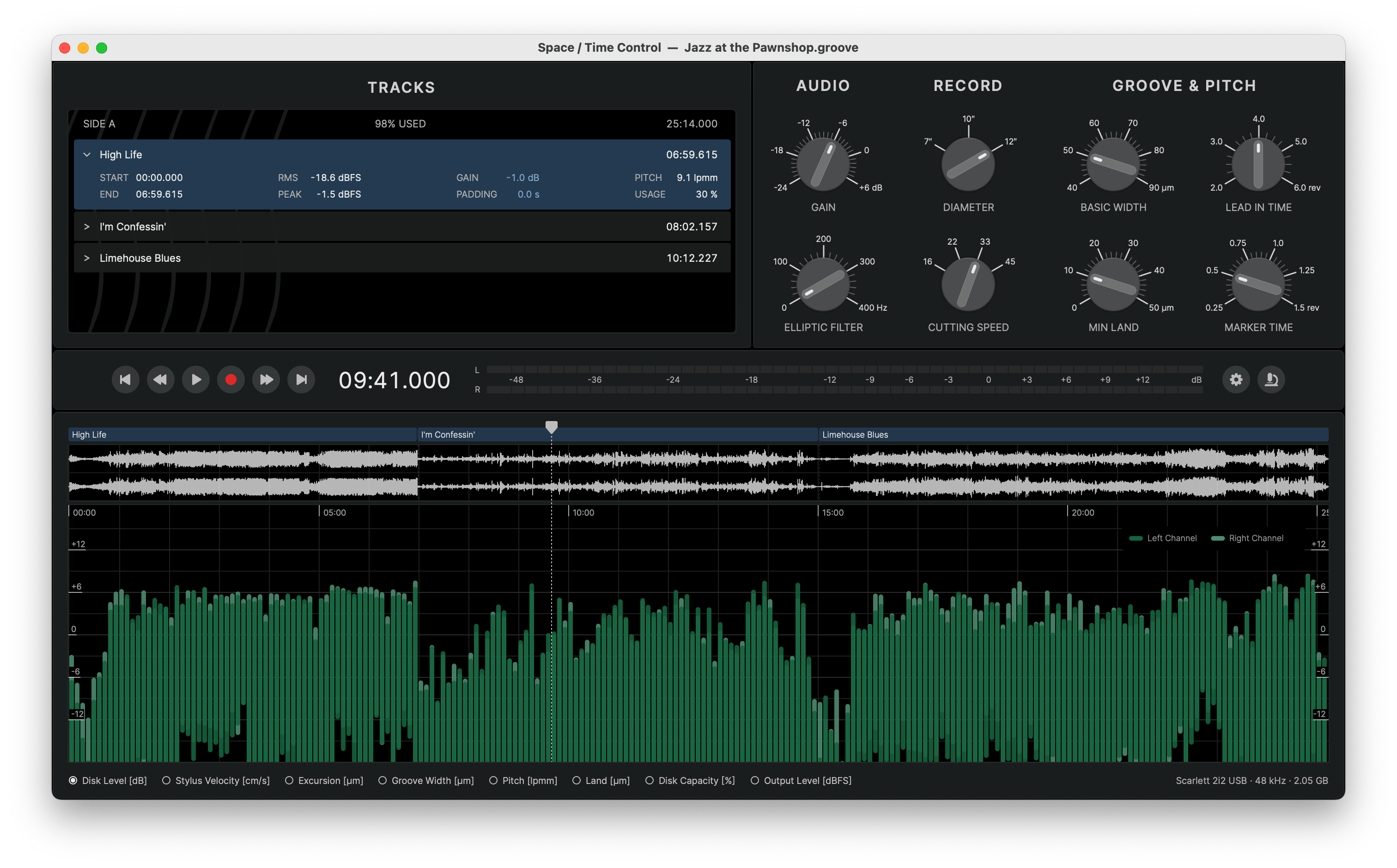
The track list displays the arrangement of program tracks for one side of the record. Currently, only one side an be processed at a time.
Once tracks have been added, the header of the track list displays this information:
- Side Label – as of this release fixed as SIDE A
- Total Disk Usage – percentage of available disk space consumed by the program
- Total Program Runtime – total duration of the program in MM:SS.mmm format
Each track entry is displayed in a collapsible list, showing basic track information by default and more details when expanded.
Managing Tracks
Adding Tracks
Tracks can be added to the track list by importing digital audio files using one of the following methods:
- Click on the empty analysis graph section to browse for files or folders
- Use the menu command to browse for files or folders
- Drag and drop files or folders directly into the application window
When adding a folder, all supported audio files within the folder and its subfolders will be imported.
Supported Audio Formats and Parameters
- File Type – .wav, .flac, .mp3, .aiff, .caf
- Sample Rate – 44.1 kHz, 48 kHz, 88.2 kHz, 96 kHz, 192 kHz
- Bit Depth – 16/24/32-bit Integer, 32/64-bit Float
- Channel Layout – Mono, Stereo
BWF Cue Markers
If an audio file contains embedded Broadcast Wave File (BWF) cue markers, STC offers the option to split the file into individual tracks at the embedded cue positions on import.
Moving Tracks
Tracks can be reordered by dragging and dropping them within the list. Multiple tracks can be selected using standard selection methods based on the operating system.
Double-clicking a track will move the playhead position to the beginning of the track.
Deleting Tracks
Tracks can be removed via the menu command:
Splitting and Merging Tracks
In case a master file contains more than one track but no embedded cue markers, the file can be split into separate tracks manually.
Using the menu command will split a track at the current playhead position.
The command allows to merge two or more selected tracks into one, if the tracks reference consecutive sections in the same audio file.
Track Information
Each track entry displays the following basic track information by default:
- Title – derived from the filename
- Duration – in MM:SS.mmm format
Clicking on the track title, allows to edit it.
Clicking the chevron icon > next to the track title expands the track info to reveal more details. Holding the ⌘ or Ctrl key while clicking expands or collapses details for all tracks simultaneously.
Detailed track information
- Start – timestamp where the track begins relative to the beginning of the side
- End – timestamp where the track ends relative to the beginning of the side
- RMS – total RMS level of the track's digital master data relative to 0 dBFS
- Peak – absolute peak level of the track's digital master data relative to 0 dBFS
- Pitch – average groove pitch in lines per mm (lpmm) that the track uses on disk
- Usage – percentage of available disk space consumed by the track
Track Settings
The expanded track view also includes two adjustable parameters:
- Gain – adjusts track level in dB
- Padding – adds silence to the end of the track
Transport and Metering

The center of the main window contains the transport and metering section as well as auxiliary controls to open the Microscope View and the Application Settings dialog.
Transport Controls
Buttons for play, pause, seek and skip enable typical navigation and transport functionality. The red record button opens the Cutting Dialog to start the cutting process when connected to the SDMS.
A large timestamp displays the current playhead position in MM:SS.mmm format. Clicking the timestamp allows direct entry of a time value to reposition the playhead.
Using the arrow keys, the playhead can be moved in various intervals for quick navigation through the audio program as the following table shows.
| Modifier Keys | Arrow Keys | ||||
|---|---|---|---|---|---|
| none | none | −1000 ms | +1000 ms | +10 smpl | −10 smpl |
| ⇧ | Shift | −100 ms | +100 ms | +1 smpl | −1 smpl |
| ⌘ | Ctrl | −10 ms | +10 ms | -- | -- |
| ⌘ + ⇧ | Ctrl + Shift; | −1 ms | +1 ms | -- | -- |
| ⌥ | Alt | Previous track | Next track | +1 revolution | −1 revolution |
When starting playback, the master audio files are played back through the Monitor Audio Device selected in the Application Settings dialog. The selected audio device is also shown in the window's lower right corner.
Metering
The stereo level meter provides a real-time preview of the analog playback disk level based on the current cutting parameters.
Like the hardware meter of the SDMS Master Control, it combines:
- VU metering – green LEDs for time averaged signal levels
- PPM metering – red LEDs for peak levels
The metering is calibrated to 0 dB = 5 cm/s Stereo (NAB).
The upper limit is +14 dB, with levels exceeding this threshold triggering bright red overload indicators. Clicking on the overload indicators resets them.
Layout Parameters
The parameter section provides control over key audio and groove layout parameters that vary on a per-project basis. These parameters are stored within the project file and will be recalled when a project is opened.
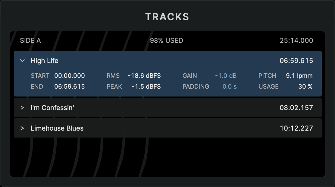
Record Parameters
The parameters in the RECORD section define the fundamental layout of the disk.
- Diameter – available record sizes (7", 10", and 12") conform to the disk geometry specifications outlined in RIAA Disc Phonograph Records for Home Use, Bulletin No. E 4 and DIN IEC 60098:2020
- Cutting Speed – standard playback speeds, 33⅓ rpm and 45 rpm, can be selected.
Groove Parameters
The parameters in the GROOVE & PITCH section define key parameters affecting the groove layout:
- Basic Width – defines the width of an unmodulated groove
- Lead-In Time – specifies the number of revolutions in the lead-in area at the start of the side. Increasing this value reduces the lead-in groove pitch to accommodate the additional revolutions. The overall lead-in area size can be adjusted with the Advanced Layout Parameters in the Application Settings dialog.
- Min Land – sets the minimum land, i.e. the spacing between adjacent grooves, maintained by the dynamic pitch algorithm.
- Marker Time – determines the duration of increased pitch for track markers. A longer marker time results in a more pronounced visual gap between tracks.
Audio Parameters
Currently, STC provides two basic audio-related parameters:
- Gain – adjusts the overall disk level of the audio program
- Elliptic Filter – applies a basic Elliptic EQ to the audio signal. The frequency value sets the filter's corner frequency. Setting the frequency to 0 disables the filter
If an elliptic filter is defined, it is applied to the monitoring audio signal on playback.
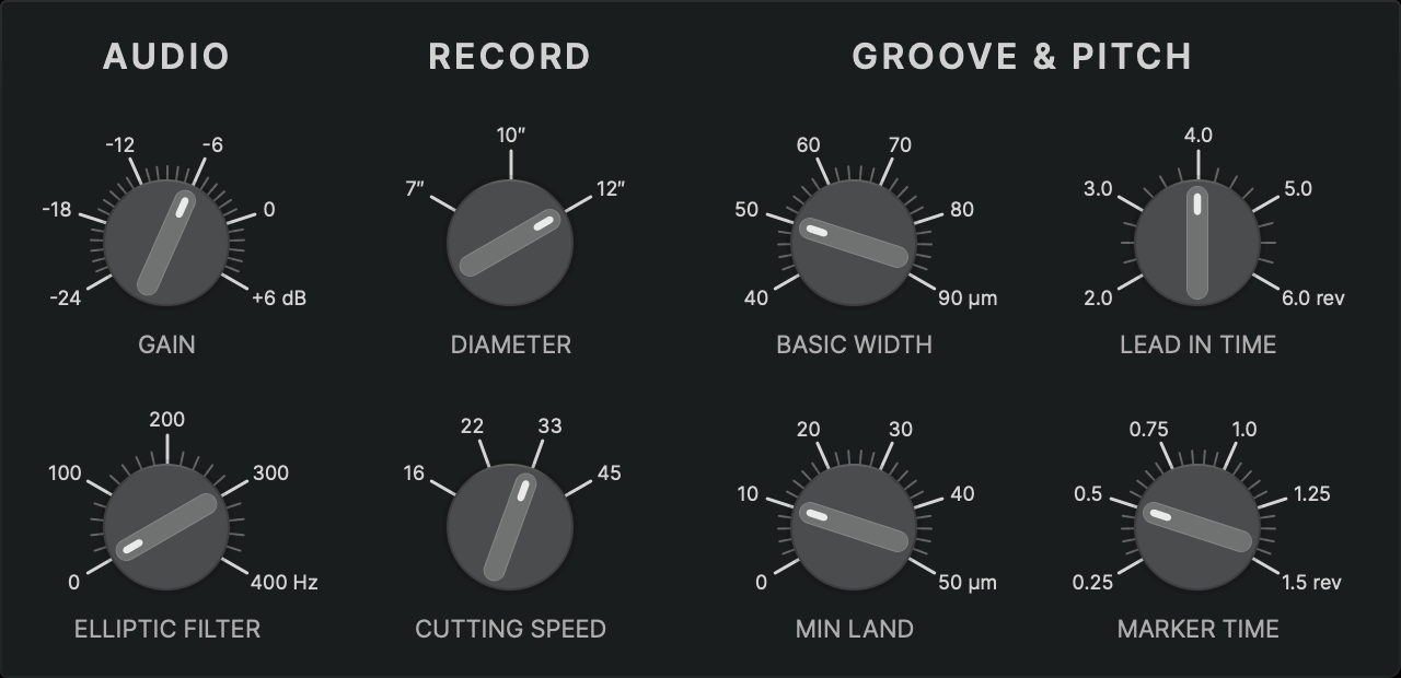
Advanced Layout Parameters
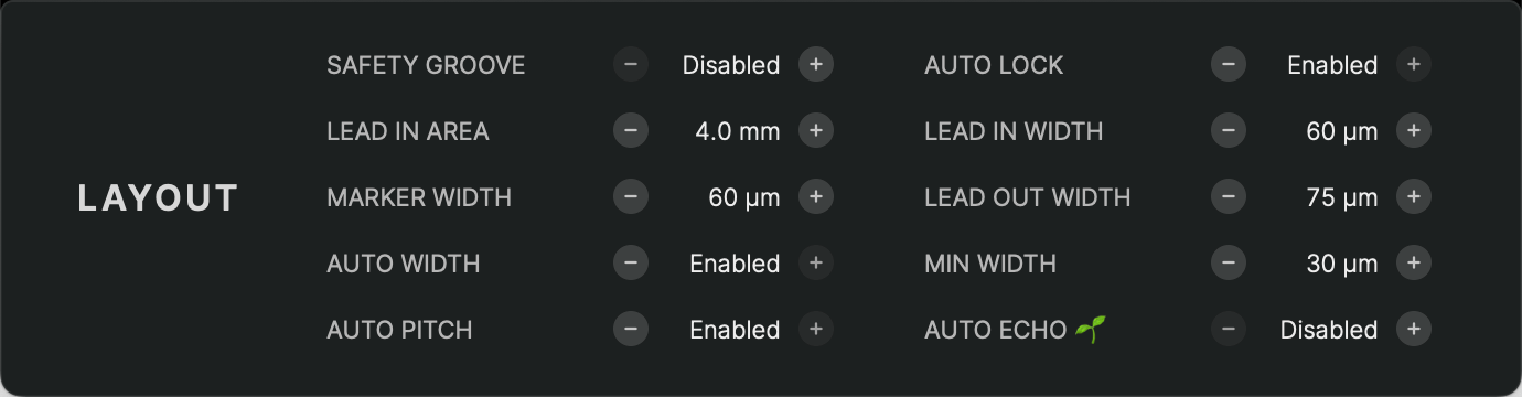
Additional layout parameters are available in the Application Settings dialog.
- Safety Groove – adds an additional, almost concentric groove before the lead-in to catch a sliding stylus. Default: Disabled
- Auto Lock – controls whether the locked groove (stopping groove) is automatically placed at the end of the lead-out. If disabled, the SDMS carriage will continue during the lead-out until manually instructed to lock, see Manual Lock. Default: Enabled
- Lead-In Area – defines the width of the lead-in section. Increasing this parameter, moves the start position of the program inward. Default: 4 mm
- Lead-In Width – defines the groove width during the lead-in. A larger width ensures secure stylus placement when manually cueing. Default: 50 µm
- Marker Width – defines the groove width during track markers. A larger width ensures safe stylus placement when dropping between tracks. Default: 50 µm
- Lead-Out Width – defines the groove width during the lead-out and locked groove section. Typically larger than the standard width to ensure stylus retention during the faster lead-out pitch. Default: 70 µm
- Auto Width – enables or disables dynamic groove width control to prevent excessively narrow grooves due to out-of-phase signals. Default: Enabled
- Min Width – specifies the minimum groove width maintained by the dynamic width control algorithm. Default: 30 µm
- Auto Pitch – enables or disables dynamic groove pitch automation. When disabled, the Min Land control in the Layout Parameters section is replaced with a control for the basic pitch of the groove. Default: Enabled
- Auto Echo🌱 – enables or disables automatic pre- and post-echo control. When enabled, the pitch is momentarily increased for passages with high level differences between adjecent parts of the groove. Default: Disabled
Groove Processing
Any change to the track list or modifications to the audio and layout parameters trigger an update of the Virtual Groove with these processing steps:
- The master audio data is mathematically transformed into a geometric representation of the modulated groove.
- This groove is then shaped into a spiral, adhering to standardized geometric parameters such as record size, groove radius limits, etc. and user-defined layout settings such as basic width, marker time, etc.
- The dynamic pitch algorithm optimizes the spiral spacing to pack the groove as tightly as possible, maximizing the runtime of the side.
- The dynamic width algorithm adjusts the groove width dynamically, expanding it where stereo information would otherwise create an excessively narrow groove.
The result is a virtual, digital preview of the analog groove the SDMS hardware would cut, based on the provided audio data and lathe settings.
This Virual Groove is then analyzed for geometric and dynamic parameters for further refinement and optimization and can be observed in the Microscope View for a detailed inspection.
Groove Analysis
The lower section of the main window presents a waveform of the audio program alongside the results of the groove analysis, arranged on a horizontal timeline.
A playhead indicates the current playback position. Clicking anywhere in the waveform or analysis graph moves the playhead to that position in time. The playhead can also be dragged with the mouse or moved in predefined intervals using the commands in the menu or keyboard shortcuts, see Transport Controls.
Zooming in and out along the timeline is possible using a scroll gesture (e.g., mouse scroll wheel) or the menu commands.
Waveform
The waveform view provides a visual representation of the left and right audio channels of the digital master with left channel on top and right channel below.
The vertical zoom is fixed, and any signal exceeding value 0 dBFS is clipped in the display.
The global audio parameters Gain and Elliptic Filter do not change the waveform representation. Track-specific parameters Gain and Padding are applied to the waveform, making it possible to preview level adjustments directly in the waveform display.
Analysis Graphs
The results of the groove analysis are visualized as floating bar graphs, where each bar represents the range of values (minimum to maximum) for a specific time segment.
When zooming out, each bar summarizes a larger set of values, providing an overview of longer time spans. Zooming in increases the resolution, offering a more detailed view of how values change over time.
For some parameters, variations are displayed within the same graph, using different colors to distinguish them. The legend, which clarifies these variations, can be toggled via .
Each analysis graph has a fixed vertical range, optimized for its specific parameter to ensure comparability of analysis results on a common scale.
The displayed analysis parameter can be changed using the radio controls at the bottom of the window or through the menu by selecting the desired parameter.
Analysis Parameters
Disk Level
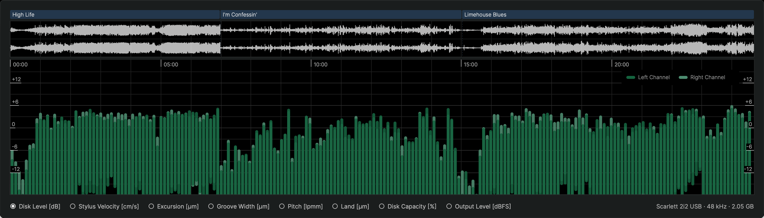
The Disk Level parameter represents the analog disk level (PPM) that the groove will reproduce on playback. It is calculated and displayed separately for the left and right channels.
The reference level follows NAB standards, where 0 dB corresponds to 5 cm/s per stereo channel. This parameter matches the metering used in the SDMS hardware.
Stylus Velocity
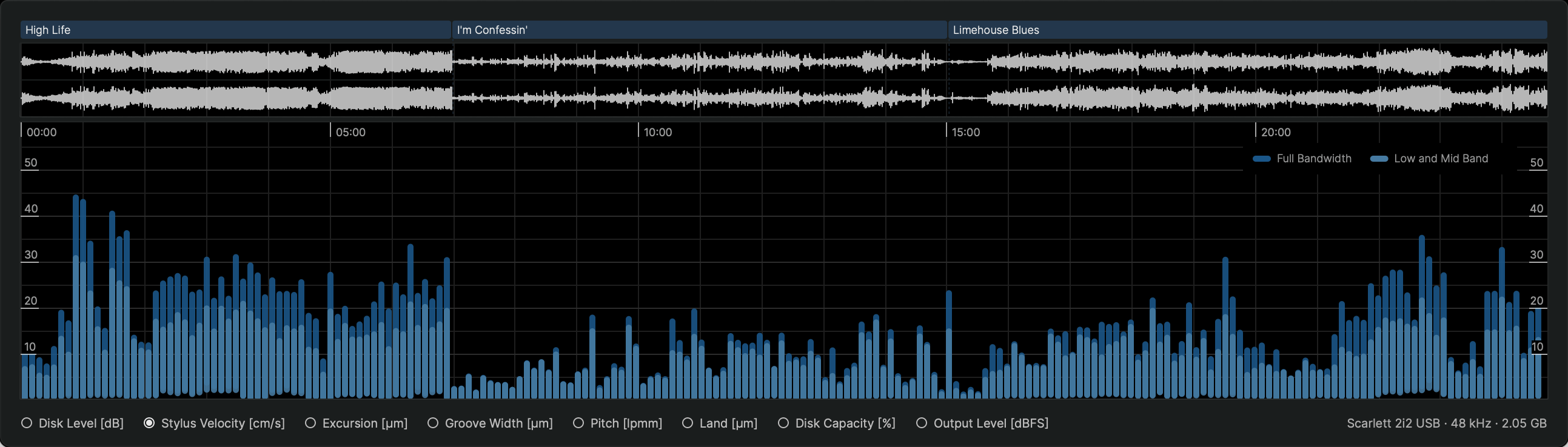
The Stylus Velocity parameter indicates the absolute velocity of a playback stylus moving in vertical and lateral directions combined during playback.
If velocity, and therefore acceleration, becomes too high, the stylus may lose contact with the groove, leading to distortion or skipping. Since velocity increases with both level and frequency, strong high-frequency audio signals such as cymbals or sibilance in a voice track are the primary causes of high velocities.
Whether a high-velocity section in the groove creates audible distortion or tracking problems depends on the material and the groove geometry at that specific location.
In general, high velocities at lower and mid frequencies tend to cause more tracking problems than those at high frequencies. To help with this distinction, the graph displays velocity for the full bandwidth as well as a filtered version for frequencies below 4 kHz.
Excursion
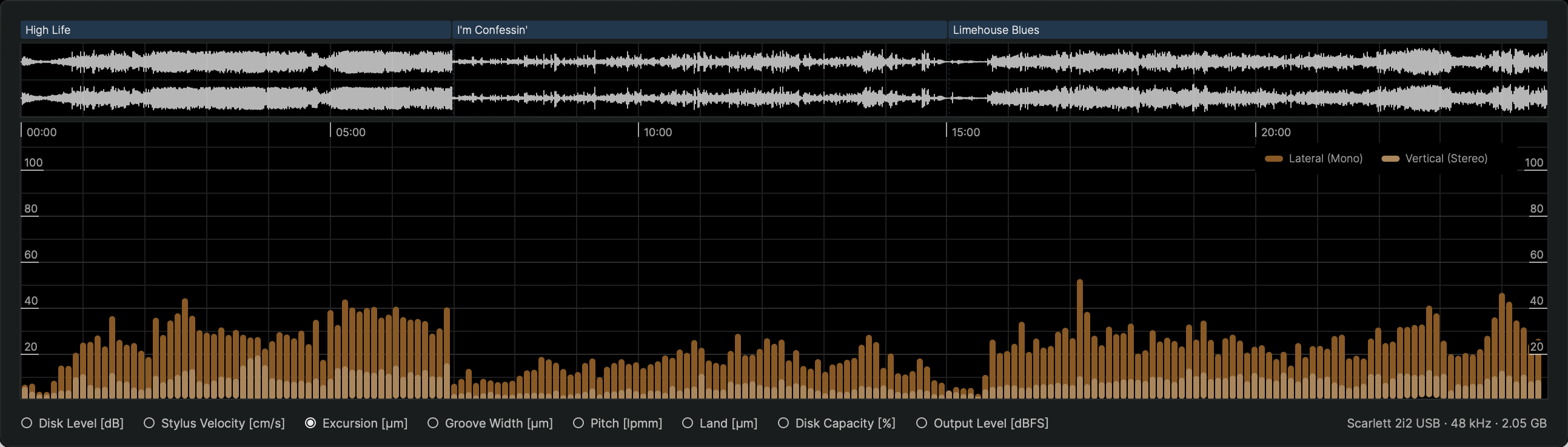
Groove modulation depends on stereo phase relationships. A mono signal, where both channels are in phase, results in purely lateral modulation, while a mono signal with one channel inverted and thus opposite phase creates purely vertical modulation. Typical stereo signals, with continuously changing phase relations, generate a combination of both lateral and vertical modulation.
The Excursion parameter graph represents the lateral and vertical components of the stylus excursion during cutting and playback.
Extreme lateral excursions require more disk space and can lead to tracking distortion due to excessive stylus velocity and acceleration. Extreme vertical excursions require dynamic width compensation and can result in grooves that are both wider and deeper than normal.
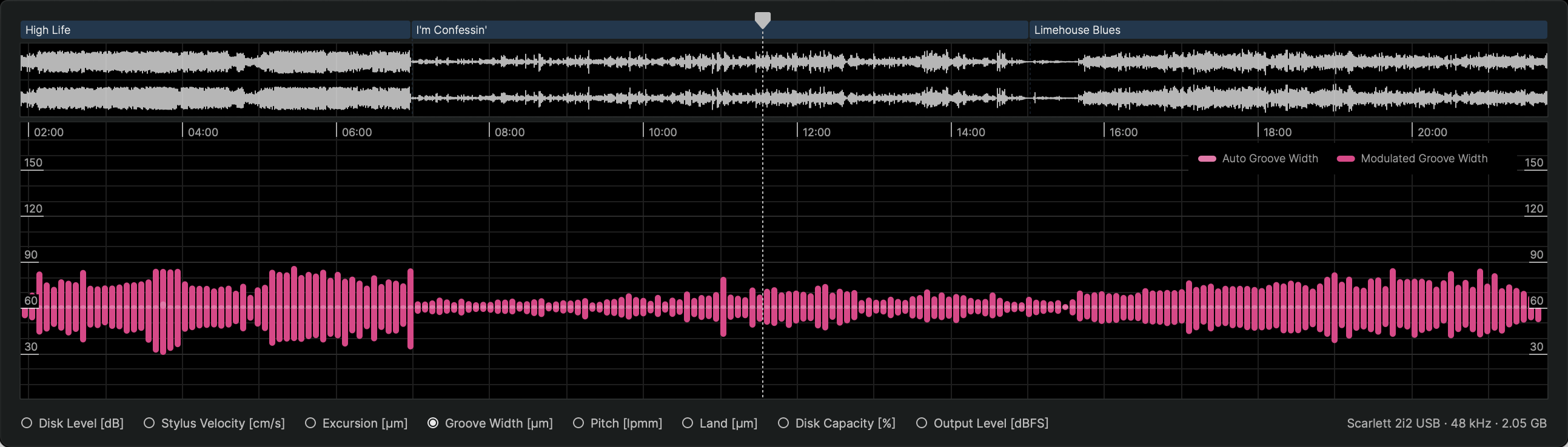
Groove Width
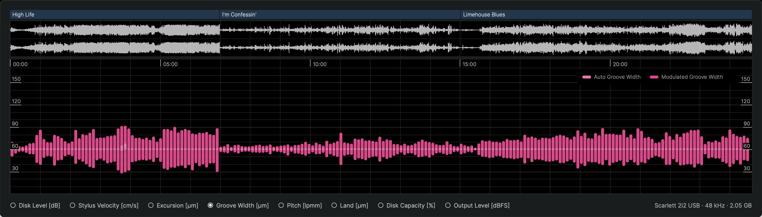
For a purely lateral mono signal, the groove width remains constant at the basic width setting. When stereo content is present, the cutting stylus also moves vertically, which modulates the groove width.
The Groove Width parameter displays the result of this vertical modulation as modulated groove width, as well as the dynamic width compensation applied to maintain the groove above the defined minimum width parameter.
Extreme vertical modulation, such as that caused by strong out-of-phase low-frequency content, can create grooves that fluctuate between extremely narrow and excessively wide. This poses challenges during both the cutting process and later pressing.
While width automation can compensate for narrow passages, it will further exaggerate wide and deep sections. In such cases, an elliptic filter can help keep the groove within acceptable parameters.
Pitch
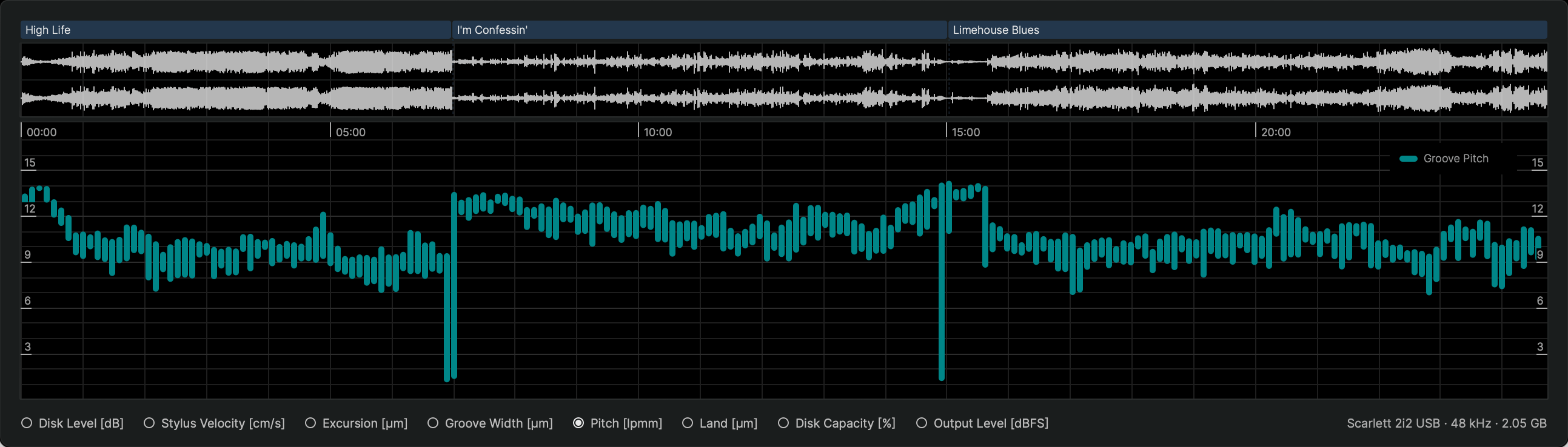
The Pitch parameter represents the adjustments made by the dynamic pitch algorithm to optimize groove spacing and maximize disk runtime. By reducing the spacing between adjacent grooves, the system ensures that as much program material as possible fits onto the disk.
The parameter is expressed in lines per millimeter of disk radius (lpmm), where lower values indicate greater spacing between grooves.
This graph does not convey critical cutting issues but serves as a visualization of how the pitch dynamically changes across different tracks.
Land
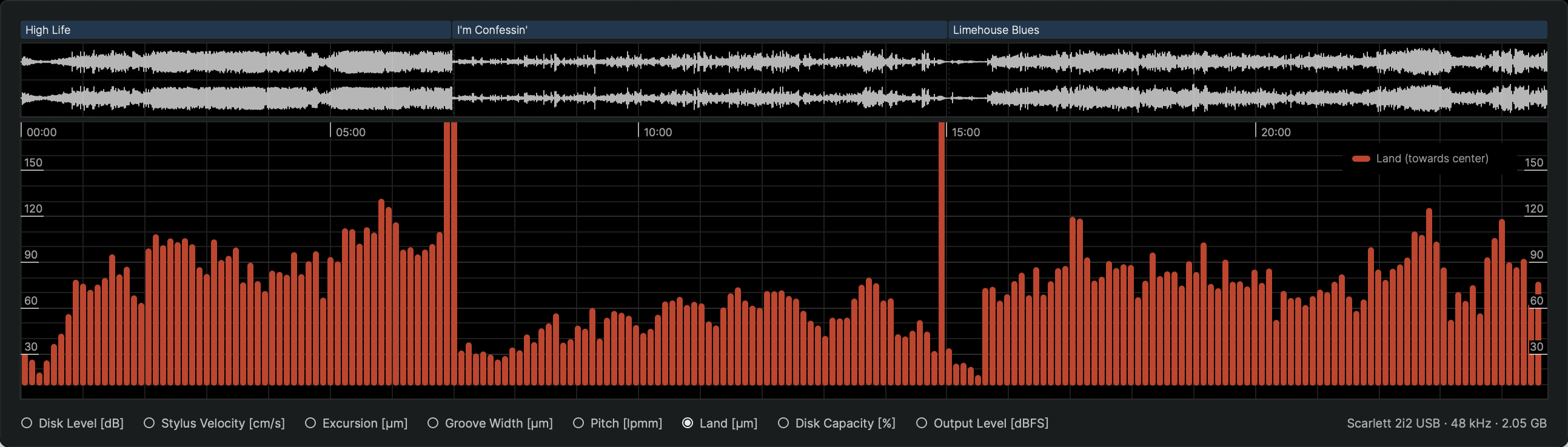
The Land parameter measures the remaining space between grooves after the dynamic pitch algorithm has been applied.
Like the pitch parameter, this information is primarily for visualization purposes and does not indicate any potential cutting issues.
Disk Capacity
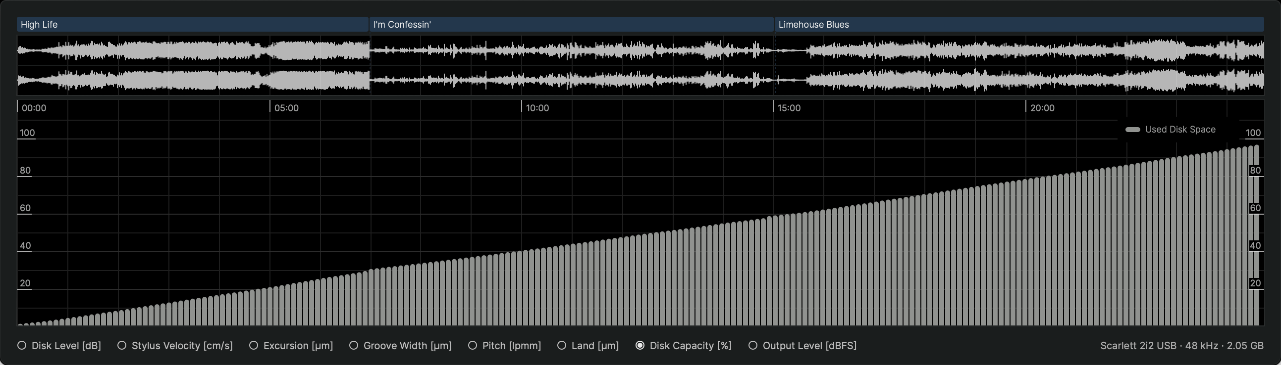
One of the fundamental challenges in record cutting is maintaining the right balance between disk capacity and disk level. A louder cut provides a better signal-to-noise ratio but requires more disk space, limiting the total program duration that can be accommodated on a single side.
The Disk Capacity graph illustrates how each track gradually fills the disk, reaching the maximum capacity defined by the standard limits for the outermost and innermost groove diameters.
Output Level
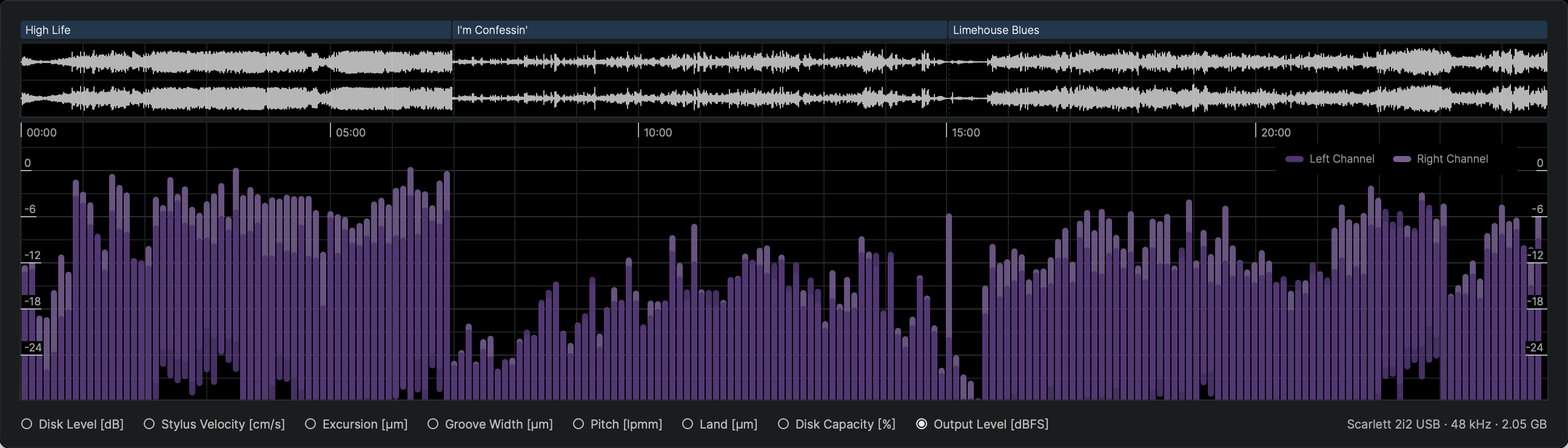
The Output Level parameter reflects the final digital signal level as it is sent to the SDMS Master Control's DAC.
This level is mainly determined by the combination of level calibration and gain settings. When using Sillitoe MMFB MKII heads, an additional Head Calibration EQ further affects the output signal level.
The graph provides a representation of the digital output level with all processing stages applied. To prevent clipping and distortion, STC enforces a strict upper limit of 0 dBFS on the output signal.
Microscope View
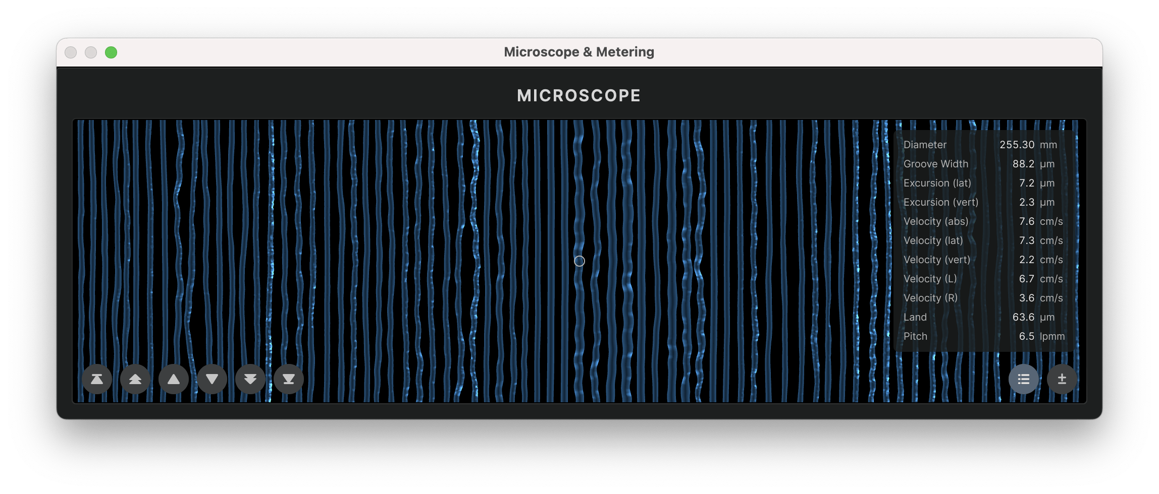
The most detailed inspection of the Virtual Groove is possible using the microscope view, which shows the calculated groove geometry with a sample-accurate resolution.
The geometric shape of the groove is overlaid with a color-mapped representation of the currently selected analysis parameter. The small circle in the center of the view indicates the current playhead position.
The Zoom of the microscope view can be toggled between 25x/50x/100x/200x, allowing for detailed inspection of the groove or a broader overview.
The Parameter List holds a list of all relevant geometric and dynamic groove parameters at the current playhead position.
Application Settings Dialog
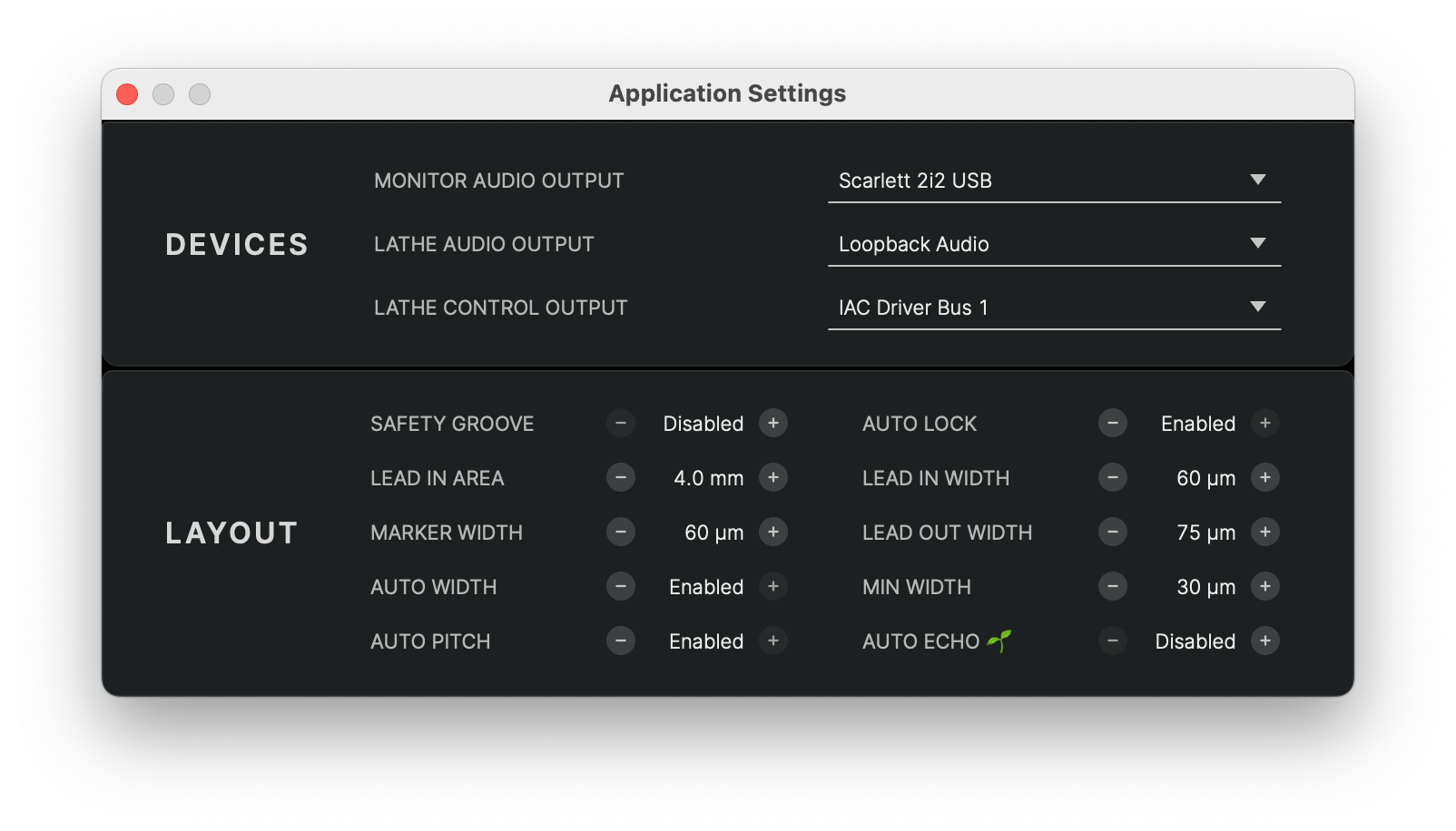
The Application Settings dialog holds a list of settings which are shared between all projects, both new and loaded from a project file.
Devices
STC allows to select three different devices for audio and control signals:
- Monitor Audio Output – audio playback device for monitoring audio when playing from the main window.
- Lathe Audio Output – audio playback device connected to the SDMS cutter head. By default, this should be the SDMS' built-in DAC, listed as SDMS Master Control.
- Lathe Control Output – hardware interface for machine control signals. This should be set to the SDMS' built-in controller, listed as SDMS Space / Time Control.
Advanced Layout Parameters
See section Advanced Layout Parameters.
Lathe Calibration Dialog
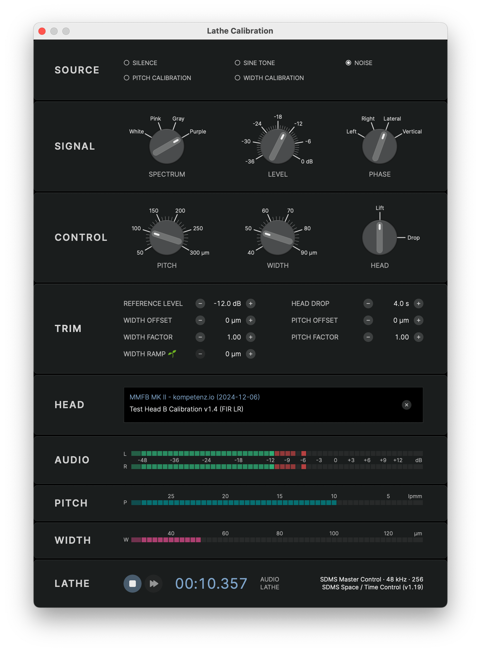
The Lathe Calibration dialog window holds a set of utilities to test and calibrate the software with the hardware of your individual lathe.
The various controls allow to manually send audio and control signals to your lathe and observe the results of the machine movement or test cuts.
For a step-by-step guide of how to calibrate your lathe, please refer to the calibration instructions or contact our support.
Signal Source
The SOURCE section allows to select an audio source signal or a predefined sequence of control signals to be sent to the lathe.
- Silence – no audio signal is sent, only the control signals for pitch and width automation are sent, cutting a silent groove
- Sine Tone – a sine tone is sent with the signal parameters defined in the Signal section
- Noise – a noise signal is sent with the signal parameters defined in the Signal section
- Pitch Calibration – a predefined control signal pattern is sent to the pitch automation system
- Width Calibration – a predefined control signal pattern is sent to the width automation system
For the predefined calibration signals, please refer to the respective calibration manuals for details: Pitch Calibration and Width Calibration.
Audio Signal Parameters
When a value of Sine tone or Noise signal is selected, the Signal section allows to define parameters for the audio signal.
- Frequency – frequency of the sine tone in Hz
- Spectrum – spectrum of the noise signal
- White – white noise with a flat spectrum
- Pink – pink noise with a -3 dB/octave spectrum
- Grey – band-passed white spectrum (50 Hz…15 kHz)
- Purple – band-passed pink spectrum (50 Hz…15 kHz)
- Level – peak signal level in dBFS
- Phase – phase correlation of left and right channel
- Left – left channel only
- Right – right channel only
- Lateral – left and right channel in phase, generating lateral stylus movement
- Vertical – left and right channel opposite phase, generating vertical stylus movement
Control Signal Parameters
The Control section allows to define parameters for the control signals sent to the lathe.
- Pitch – fixed pitch signal sent to the pitch automation system, measured as realtive distance of two adjacent grooves in µm
- Width – groove width signal sent to the width/depth automation system of the cutter head
- Head – lift or drop signal sent to the cutter head
Trim Parameters
The parameters in the Trim section define the behavior of your particular lathe to the control signals sent by STC. Please refer to the calibration instructions how to find the correct values for your lathe.
- Reference Level – digital peak level of a 1 kHz sine tone sent to the cutterhead which creates a groove with 0 dB analog disk level at 5 cm/s (NAB)
- Head Drop – timeout for the mechanical head drop, i.e. time it takes the head from receiving the drop signal to touching the surface of the disk. This defines the time STC waits after the head drop signal before sending any dynamic pitch or width signals to the SDMS hardware.
- Pitch Offset and Pitch Factor –parameters of the dynamic pitch automation as result of the Pitch Calibration procedure
- Width Offset and Width Factor – parameters of the dynamic width/depth automation as result of the Width Calibration procedure
- Width Ramp🌱 – amount of gradual width compensation towards the inner diameter of the disk. This tries to counterbalance the effect of groove growth towards the inner diameter of the disk due to a slower relative speed of cutterhead and disk. In its current implementation, this gradually increases the land towards the center in order to allow for the slight increase in groove width without risking overcuts.
Head Calibration
The Sillitoe MMFB MKII head requires a calibration EQ to be applied to the output signal to achieve a perfectly flat frequency response and best possible cutting results.
The head calibration EQ along with other calibration settings are contained in a .head calibration file created for your specific lathe during the initial setup process. Please contact our support to obtain your calibration file if you have not received it automatically.
To apply the head calibration, drag the .head file onto the Head section or select the file from the file dialog.
The head calibration will be copied and stored with the other calibration settings. When loaded successfully, the Head section will display the name and version of the calibration.
Signal Metering
When sending signals to the SDMS hardware from the calibration dialog, the metering sections display the current audio level and control signal values:
- Audio – output level of the audio source signal (pre head calibration filter)
- Pitch – pitch value sent to the pitch automation system in lpmm
- Width – width value sent to the width/depth automation system in µm
Lathe Controls and Lathe Information
The Lathe section displays information about the connected SDMS hardware modules and has basic transport controls to start and stop sending audio and control signals to the lathe:
- Record – start/stop sending audio and control signals to the lathe
- Fast Forward – move the carriage while holding down the button
Next to the timestamp, information about the connected SDMS hardware modules is displayed:
- Audio – connected lathe audio output device with current sample rate and output buffer size
- Control – connected SDMS control device with the current firmware version
If one or both hardware connections are lost, the device info will be change color to red and the transport controls will be disabled.
System Firmware

When the calibration dialog is opened and the SDMS hardware modules are connected, STC automatically checks for available firmware updates in the background.
If an update is available, an additional System section will be displayed, showing the current version number, the available version update and a button to download and apply the update.
Cutting Dialog
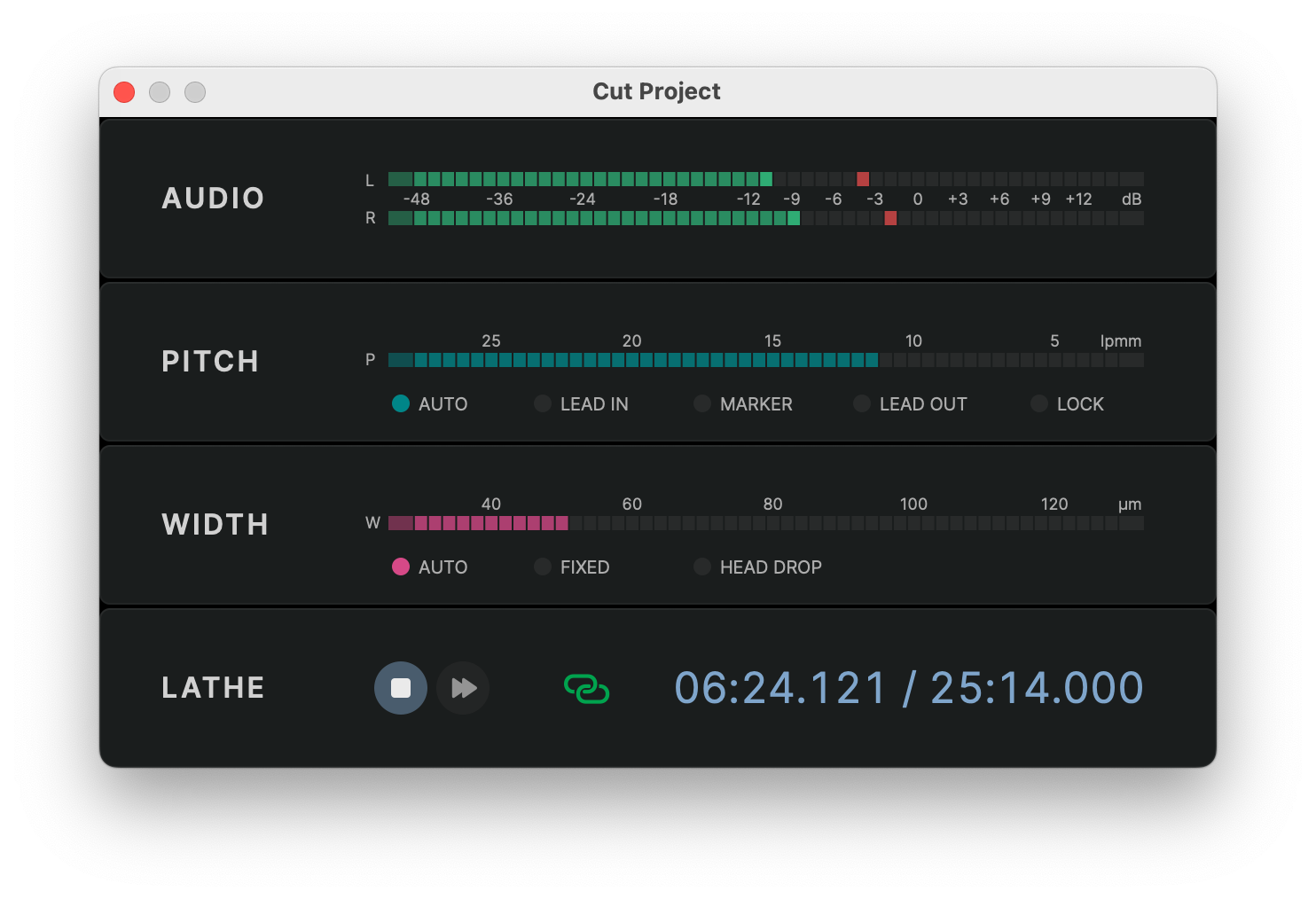
Metering
The dialog shows three meters to monitor the cutting process:
- Audio – analog disk level of the audio program signal relative to the 5 cm/s (NAB) reference level
- Pitch – pitch signal sent to the pitch automation system in lpmm
- Width – width signal sent to the width/depth automation system in µm
The Pitch section also displays the current pitch automation phase with five status LEDs:
- Auto – pitch automation is active and the pitch is adapted dynamically
- Lead-In – fixed pitch during the lead-in groove
- Marker – fixed pitch during a track marker
- Lead-Out – fixed pitch during the lead-out groove
- Lock – zero pitch during the locked groove
The Width section also features three status LEDs to indicate the current width automation state:
- Auto – width automation is active and the width is adapted dynamically
- Fixed – fixed width during the lead-in, lead-out and track marker grooves
- Head Drop – no width signal is sent during the head drop timeout
Lathe Controls
In the Lathe section, the cutting dialog has two buttons to control the cutting process:
- Record – starts the cutting process
- Fast Forward – moves the carriage while holding down the button
The fast forward button can be used to move the carriage to the start position. The speed of the carriage movement will increase in steps while holding down the button.
When the record button is pressed, the cutting process will start automatically and the button will be displayed as Stop.
The timestamp next to the fast forward button displays the current cutting position and the total duration of the audio program.
- During the head drop and lead-in phase, the timestamp will count up from negative values to zero at the start of the program.
- During the program, the timestamp will count up continuously until the program is complete.
- After the program, the timestamp will continue to count up until it has finished the lock groove.
A small link icon next to the timestamp indicates the status of the connection to the SDMS hardware modules:
- If both the audio and the control device are connected, the status will be displayed as a green link and the record buttons will be enabled.
- If one of the devices is not connected, the link icon will display an error icon and the record buttons will be disabled.
- Clicking on the link icon will trigger a manual refresh of the connection status.
Test Cuts
While the normal cutting process starts with the lead-in and then proceeds to cut the whole program, it is also possible to test cut only a custom section of the program.
- To initiate a test cut, position the playhead at the start of the section to be tested before opening the cutting dialog
- In the cutting dialog, hold down the Shift key when clicking on the record button. The record button will change from red to blue to indicate that a test cut will be started
- Pressing the blue record button will initiate a test cut at the current playhead position without a lead-in or lead-out
- The cut can be stopped manually at any time or will stop automatically at the end of the program
Manual Lock
If the Auto Lock setting is disabled in the Advanced Layout Parameters, the position of the lock groove has to be triggered manually:
- Before the cut starts, a warning is displayed to remind the user that the auto lock feature is disabled
- The program will be cut normally beginning with the lead-in and continue until reaching the lead-out section
- When the cut enters the lead-out, the icon of the stop button changes to a small padlock icon indicating that the system is waiting for a manual lock command
- The carriage will continue at lead-out pitch until it receives the manual lock command
- The manual lock should be triggered when the carriage reaches the LOCK position on the SDMS RIAA Disk Diameter scale
- As soon as the manual lock is triggered by clicking the padlock button, the carriage will stop and cut the locked groove
- When the locked groove is complete, the cutter head lifts and the cutting process ends
Miscellaneous
Keyboard Shortcuts
All menu commands have corresponding keyboard shortcuts that can substantially speed up the navigation through the application. The shortcuts are displayed in the menu bar next to each command.
Most interactive user interface elements have keyboard shortcuts assigned as well. The shortcuts are displayed as tooltips when hovering over the element.
License Handling
STC uses a personalized license file to activate the software. The license file is requested on first launch and stored in the user library folder. If the license file is lost, please contact our support to obtain a replacement.
The license is activated and validated in regular intervals with the STC license server. This happens automatically in the background and requires an internet connection and a valid system clock.
A purely offline licensing scheme is currently not supported. If you have such a requirement, please contact our support.
Project File Format
The .groove project file format is a binary container format that bundles audio files and settings. It should not be edited manually.
New versions of STC will maintain compatibility with project files from previous versions, but there might be issues with specific features. Project files saved with a newer version of STC might not be compatible with an older version of STC.
Log Files
STC writes a separate text file for each launch with debug and error messages to the user library folder. Each file is named with the current date and time.
The log files are useful for diagnosing issues and can be sent to our support team to help with troubleshooting. The log file for the current launch can be opened using the menu item .
