Preface
The goal of pitch calibration is to align the pitch signal sent by the software with the actual movement of the carriage lead screw.
Any offset between the pitch signal and the resulting pitch on the disk is too small to measure directly from a groove. The best approach is to drive the carriage at a constant pitch for several hundred revolutions and measure the cumulative error.
This calibration takes some time but is semiautomated, so you don't need to be present throughout the process.
Prerequisites
None.
Abbreviations
- SDMS
- Sillitoe Disk Mastering System hardware
- STC
- Space / Time Control software
References
Calibration Procedure
Travel Distance Calibration
Prepare STC and SDMS:
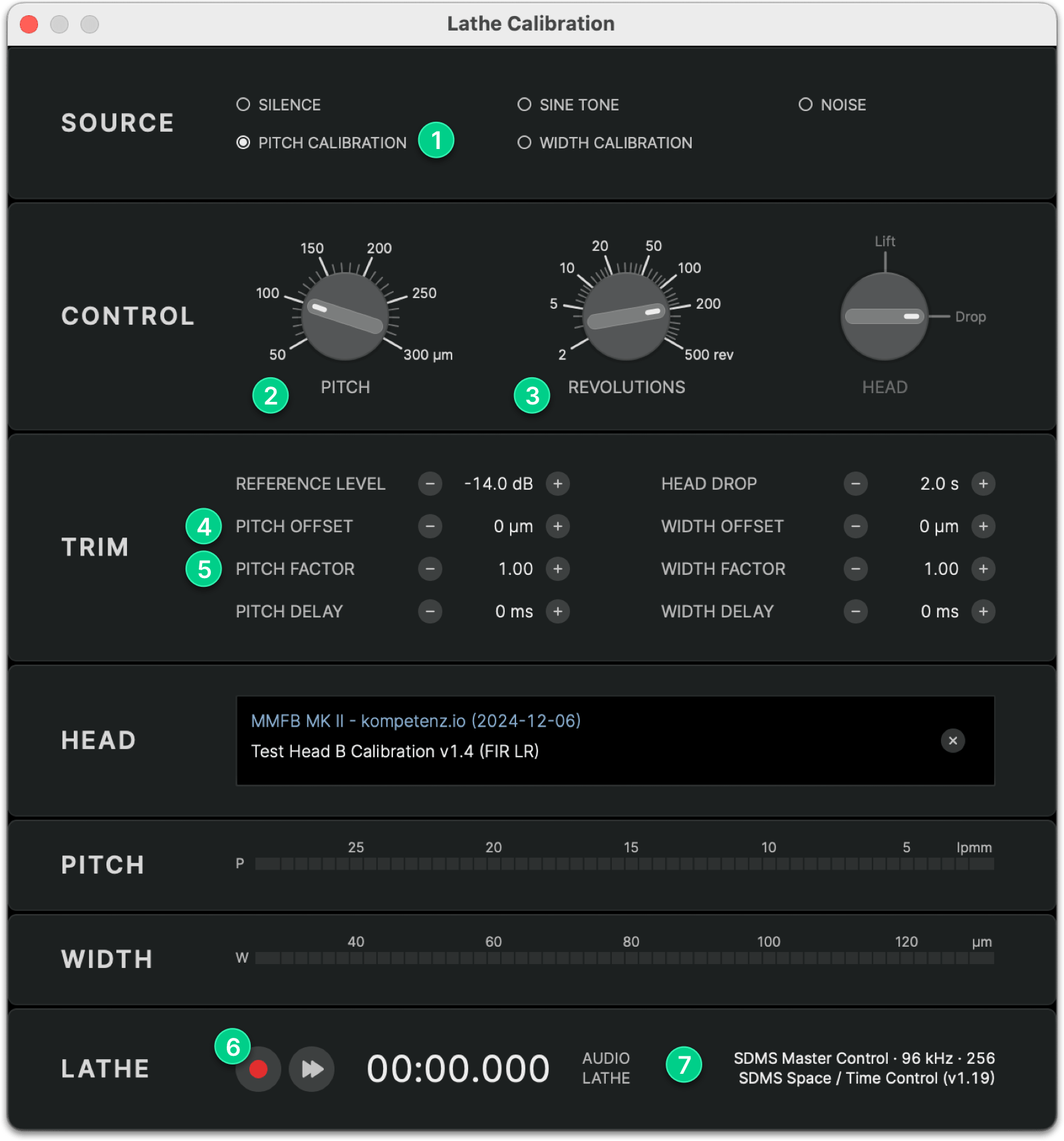
- Launch STC and open the Lathe Calibration dialog
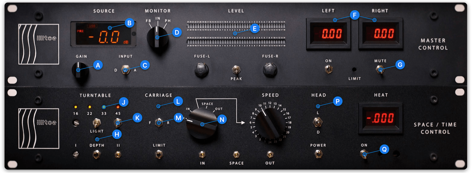
- Confirm your SDMS Master Control and Space / Time Control hardware modules are connected 7
- Select PITCH CALIBRATION 1 in the SOURCE section and set REVOLUTIONS 3 to 200 rev
- Reset PITCH OFFSET 4 to 0 µm and PITCH FACTOR 5 to 1.00
- Disable automation for DEPTH H, CARRIAGE L, and HEAD P (LED buttons OFF)
Repeat the following steps for each pitch value in the table below:
- Disable CARRIAGE L automation (LED button OFF)
- Use the XISOX N switch to move the carriage to the 300 mm mark on the RIAA DISK DIAMETER scale as precisely as possible
- Enable CARRIAGE L automation (LED button ON)
- Set the PITCH 2 control to the next pitch value in the table
- Press REC 6 to start the calibration procedure
- Observe as the carriage moves and the timer counts down from 06:00.000
- After the test completes, note the diameter where the carriage stops (or take a picture)
| PITCH | # REV | START Ø | STOP Ø |
|---|---|---|---|
| 100 µm | 200 | 300 mm | |
| 150 µm | 200 | 300 mm | |
| 200 µm | 200 | 300 mm | |
| 250 µm | 200 | 300 mm | |
| 300 µm | 200 | 300 mm |
Once all tests are complete, send the results to calibration@spacetimecontrol.com for evaluation of your PITCH FACTOR and PITCH OFFSET parameters.
Pitch Calibration Project
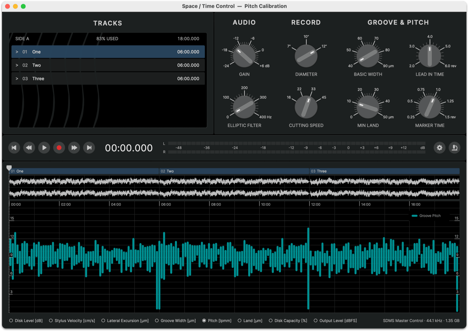
To fine-tune your pitch calibration, use the Pitch Calibration Project, an 18-minute test program containing noise with strong low-frequency modulation. This program generates a variable pitch signal representative of typical music cuts.
You can download the Pitch Calibration groove file here (20 MB).
Running the Pitch Calibration Project
- Launch STC and open the project
Pitch Calibration.groove - Adjust the GAIN control in STC until the program uses 83% disk capacity; leave all other settings at their defaults
- Disable automation for DEPTH H, CARRIAGE L, and HEAD P (LED buttons OFF)
- Ensure the head is muted G
- Use the XISOX N switch to move the carriage to the 12" START position at 298 mm
- Enable CARRIAGE L automation (LED button ON)
- Ensure the carriage direction switch M is set to F(orward)
- Open the Cut Project dialog in STC and press REC to start the test run
- After the test is complete, the carriage will stop at the lock groove position
- If the pitch calibration is correct, the carriage should stop within ±1 mm of the 12" LOCK mark (Ø 106.4 mm) on the RIAA DISK DIAMETER scale
Fine-Tuning the Pitch Offset
If the carriage stop position deviates by more than ±1 mm, adjust the PITCH OFFSET 4 in the Lathe Calibration dialog:
- If the carriage stops at a smaller diameter (overshoots), decrease the pitch offset
- If the carriage stops at a larger diameter (undershoots), increase the pitch offset
To calculate the adjustment, use the following formula:
Pitch Offset Delta = (Measured Lock Groove Diameter − 106.4 mm) / 1.22
Measured Lock Groove Diameter = 100 mm
Pitch Offset Delta = (100 mm − 106.4 mm) / 1.22 = −5 µm
You can also use this fine-tuning procedure with any of your own groove projects; the lock groove position should always be identical regardless of the audio content of the program.
Troubleshooting
If you experience variations in the stop-groove position in your cuts, double-check these parameters:
- Tension of the pitch motor belt
- Alignment of pitch motor pulley and lead screw pulley
- PITCH OFFSET and PITCH FACTOR values in STC
Whenever you make changes to the pitch motor hardware (belt, pulleys, etc.), it is recommended to check the pitch calibration again.
